148
Example 2:
Lifetime enhancement of
power modules – Project ongoing. The
lifetime of power modules is determined
by the junction temperature cycle. In order
to increase the lifetime the junction tem-
perature swing must be reduced. EP has
developed a power module adopter that
can be placed between the baseplate of
the power module and cooling element.
This adopter is changing the local ther-
mal impedance actively for each individual
chip. This allows full active control of the
junction temperature for each chip, thus
reducing the temperature swing. A 30%
reduction of the temperature swing can
be observed with the potential to go up to
70%. The adopter communicates with the
gate drive circuit directly and impinges the
cooling fluid in a controlled manner with-
out the use of a mechanical pump.
Newcastle University can trace its origins
back to 1834 and is now in the top 1%
of world universities (QS World Rankings).
We are member of the Russell Group, the
association of the 20 leading research-in-
tensive UK universities and we have one
of the largest European Union research
portfolios in the UK. The Electrical Power
Research Group (EP) is UK’s most active
academic research institution in research
on novel electromagnetic devices, power-
dense power electronics and derived sys-
tems, estimation and control methods and
advanced smart grids. Research activities
cover various applications such as small
low-cost drives for household applications
to high efficient high power multilevel
converters. EP is very active in automotive,
aerospace and smart grid applications,
working closely together with OEMs, Tier
1 and Tier 2 suppliers on new cost-effec-
tive solutions. The Group comprises 14
members of academic staff, supported by
approximately 22 Research Associates and
50 PhD students, with a strong record on
publications, patents and exploitations.
60% of our project funding comes directly
from industry and EP’s role is to assist in-
dustry in the creation and maintenance of
market lead new products.
Example 1:
Power dc/dc converter –
Project ongoing. This project addresses
the need to build smaller passive compo-
nents for power dc/dc converters. Tradi-
tional techniques are making use of high
switching frequency devices or are devel-
oping new materials to reduce the size of
passive components. Regrettably, these
solutions are leading to high cost and suf-
fer from the unknown of reliability data.
EP developed a step-change in designing
dc/dc converters by introducing new de-
sign rules. These design rules led to a new
and simple control method that keeps the
output voltage and inductor current sta-
ble even at a reduced inductor size. Work
presented so far shows a reduction in the
inductor size of a dc/dc converter by 50%
only by changing the control algorithm
but without the use of new materials or
increasing the switching frequency. There-
fore this technique is seen as a cost-effec-
tive method to reduce the size and weight
of passive components.
Newcastle University upon Tyne
Inverter for a doubly-fed induction generator
High efficient drive for a solar powered plane
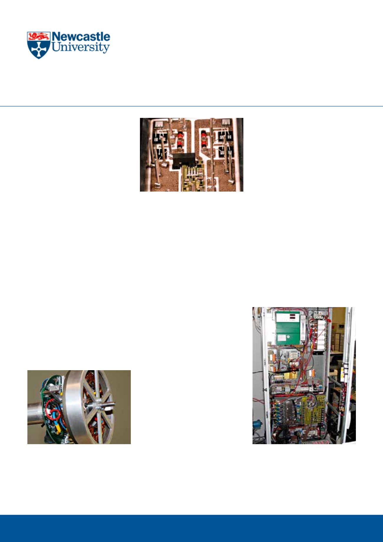
Power module for a fault tolerant drive


